Infill
Infill is the internal structure of a 3D print, providing strength and support. It can be adjusted to balance material usage, print time, and part strength.
- Sparse infill density
- Fill Multiline
- Direction and Rotation
- Infill Wall Overlap
- Apply gap fill
- Filter out tiny gaps
- Anchor
- Internal Solid Infill
- Extra Solid Infill
- Sparse Infill Pattern
- Credits
Sparse infill density
Variable: sparse_infill_density.
Infill density determines the amount of material used to fill the interior of a 3D print. It is usually expressed as a percentage, with 100% being completely solid.
- Higher density increases
- Strength
- Material usage
- Print time.
Note
Density usually is calculated as a % of the total infill volume, not the total print volume.
Nevertheless, not all patterns interpret density the same way, so the actual material usage may vary.
You can see each pattern's material usage in the Patterns section.
Fill Multiline
Variable: fill_multiline.
This setting allows the selected infill pattern to be generated using up to 10 parallel extrusion lines per path, while preserving both the defined infill density and the overall material usage.
To check which patterns support multiline infill, see the Patterns Quick Reference table in the Infill Patterns Wiki List or each pattern's specifics in the Patterns section.
Note
Orca's approach is different from other slicers that simply multiply the number of lines and material usage, generating a denser infill than expected.
Orca Slicer keeps the cross-section constant for the set density.
| Infill Density % | Infill Lines | Orca Density | Other Slicers Density |
|---|---|---|---|
| 10% | 2 | 10% | 20% |
| 25% | 2 | 25% | 50% |
| 40% | 2 | 40% | 80% |
| 10% | 3 | 10% | 30% |
| 25% | 3 | 25% | 75% |
| 40% | 3 | 40% | 100% |
| 10% | 5 | 10% | 50% |
| 25% | 5 | 25% | 100% |
| 40% | 5 | 40% | 100% |
Use cases
- Increasing the number of lines (e.g., 2 or 3) can improve part strength and print speed without increasing material usage.
- Fire-retardant applications: Some flame-resistant materials (like PolyMax PC-FR) require a minimum printed wall/infill thickness—often 1.5–3 mm—to comply with standards. Since infill contributes to overall part thickness, using multiple lines helps achieve the necessary thickness without switching to a large nozzle or printing with 100% infill. This is especially useful for high-temperature materials like PC, which are prone to warping when fully solid.
- Creating aesthetic infill patterns (like Grid or Honeycomb) with multiple line widths—without relying on CAD modeling or being limited to a single extrusion width.
- Increase stability for weak infill patterns like Lightning.
- Printing gears and other mechanisms, because multiline infill transfer torque better.
Strategy
The way multiple lines are generated depends on the selected infill pattern.
The following describes possible strategies for infill generation.
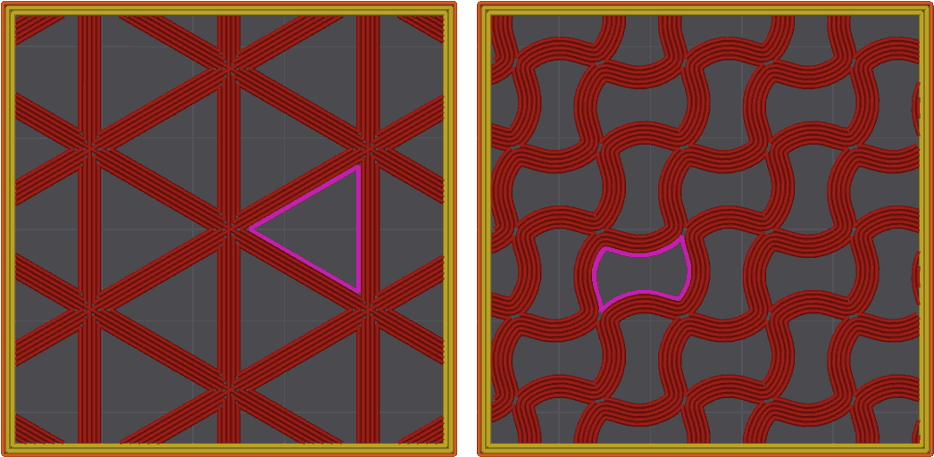
Classic Strategy
For most self intersecting infills (e.g. Cubic) multiline will generate closed loops to avoid overlapping lines. This may lead to some increased print time.
In this example of Cubic and Gyroid patterns, you can see (in purple) the closed loops generated to avoid overlapping lines.
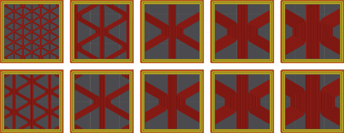
Non-Crossing Strategy
Grid & Triangles patterns use a Non-crossing multiline strategy.
For these infill patterns, an alternative approach is used, generating trapezoidal trajectories designed to avoid self-intersections of the infill lines. In each layer, the pattern rotates to ensure isotropic strength.
This strategy improves printing times by avoiding closed loops in favor of continuous printing paths.
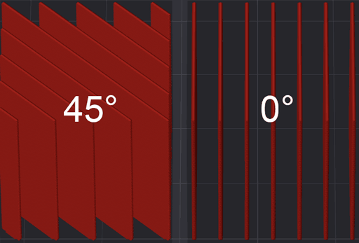
Direction and Rotation
These settings control the orientation of the sparse infill lines to optimize strength and material usage.
Direction
Mode: Advanced.
Variables: infill_direction, solid_infill_direction.
Controls the direction of the infill lines to optimize or strengthen the print.
Rotation
This parameter adds a rotation to the sparse infill direction for each layer according to the specified template.
The template is a comma-separated list of angles in degrees.
For example:
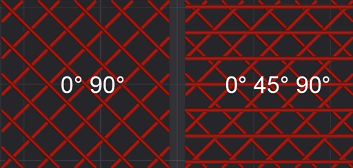
The first layer uses 0°, the second uses 90°, and the pattern repeats for subsequent layers.
Other examples:
Note
If there are more layers than angles, the sequence repeats.
Tip
You can use Template Metalanguage for infill rotation to create more complex patterns.
Important
Not all sparse patterns support rotation.
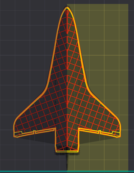
Symmetric infill Y axis
Mode: Advanced.
Variable: symmetric_infill_y_axis.
When enabled, the infill pattern will be mirrored along the Y-axis of the print bed. This can help achieve more uniform strength distribution in certain geometries.
Important
This setting may not be supported by all infill patterns.
You can apply this setting with multiple objects or using modifiers to control infill orientation for different parts of your print.
For example, you might want to mirror the infill pattern for specific components to enhance their structural integrity like planes's wings or boat hulls without the need of using 45° rotation.
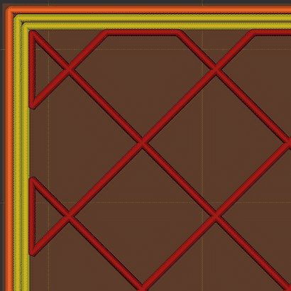
Infill Wall Overlap
Mode: Advanced.
Variable: infill_wall_overlap.
Infill area is enlarged slightly to overlap with wall for better bonding. The percentage value is relative to line width of sparse infill. Set this value to ~10-15% to minimize potential over extrusion and accumulation of material resulting in rough surfaces.
- Infill Wall Overlap Off

- Infill Wall Overlap On

Apply gap fill
Mode: Advanced.
Variable: gap_fill_target.
Enables gap fill for the selected solid surfaces.
The minimum gap length that will be filled can be controlled from the filter out tiny gaps option.
- Everywhere: Applies gap fill to top, bottom and internal solid surfaces for maximum strength.
- Top and Bottom surfaces: Applies gap fill to top and bottom surfaces only, balancing print speed, reducing potential over extrusion in the solid infill and making sure the top and bottom surfaces have no pinhole gaps.
- Nowhere: Disables gap fill for all solid infill areas.
Note that if using the classic perimeter generator, gap fill may also be generated between perimeters, if a full width line cannot fit between them. That perimeter gap fill is not controlled by this setting.
If you would like all gap fill, including the classic perimeter generated one, removed, set the filter out tiny gaps value to a large number, like 999999.
However this is not advised, as gap fill between perimeters is contributing to the model's strength. For models where excessive gap fill is generated between perimeters, a better option would be to switch to the arachne wall generator and use this option to control whether the cosmetic top and bottom surface gap fill is generated.
Filter out tiny gaps
Mode: Advanced.
Variable: filter_out_gap_fill.
Don't print gap fill with a length is smaller than the threshold specified (in mm).
This setting applies to top, bottom and solid infill and, if using the classic perimeter generator, to wall gap fill.
Anchor
Mode: Advanced.
Variables: infill_anchor_max, infill_anchor.
Connect an infill line to an internal perimeter with a short segment of an additional perimeter. If expressed as percentage (example: 15%) it is calculated over infill extrusion width.
OrcaSlicer tries to connect two close infill lines to a short perimeter segment. If no such perimeter segment shorter than this parameter is found, the infill line is connected to a perimeter segment at just one side and the length of the perimeter segment taken is limited to infill_anchor, but no longer than this parameter. If set to 0, the old algorithm for infill connection will be used, it should create the same result as with 1000 & 0.
- Anchor Off

- Anchor On
Internal Solid Infill
Variable: internal_solid_infill_pattern.
Line pattern of internal solid infill. If the detect narrow internal solid infill be enabled, the concentric pattern will be used for the small area.
Extra Solid Infill
Mode: Advanced.
Variable: extra_solid_infills.
Insert extra solid infills at specific layers to add strength at critical points in your print. This feature allows you to strategically reinforce your part without changing the overall sparse infill density.

The pattern supports two formats:
Interval Pattern
- Simple interval:
N- Insert 1 solid layer every N layers, equal toN#1 - Multiple layers:
N#K- Insert K consecutive solid layers every N layers - Optional K:
N#- Shorthand forN#1
Examples:
5 or 5#1    # Insert 1 solid layer every 5 layers
5#          # Same as 5#1
10#2        # Insert 2 consecutive solid layers every 10 layers
Explicit Layer List
Specify exact layer numbers (1-based) using comma-separated values. Each entry may be a single layer N or a range N#K to insert K consecutive solid layers starting at layer N:
1,7,9       # Insert solid layers at layers 1, 7, and 9
5,15,25     # Insert solid layers at layers 5, 15, and 25
5,9#2,18    # Insert at 5; at 9 and 10 (because #2); and at 18
Note
- Layer numbers are 1-based (first layer is layer 1)
#Kis optional in both interval and explicit list entries (N#equalsN#1)- Solid layers are inserted in addition to the normal sparse infill pattern
Tip
Use this feature to:
- Add strength at stress concentration points
- Reinforce mounting holes or attachment points
- Create internal structure for functional parts
- Add periodic reinforcement for tall prints
- Insert a single solid layer at a specific height by using an explicit list with a leading 0, which will be ignored because layer indices are 1-based. Example:
0,15inserts a solid layer only at layer 15.
Warning
Layers that include solid infill can take significantly longer than surrounding layers. This time differential may lead to z-banding-like bulges. Consider adjusting cooling or speeds if you observe artifacts.
Sparse Infill Pattern
Variable: sparse_infill_pattern.
Tip
See Infill Patterns Wiki List with detailed specifications, including their strengths and weaknesses.
Credits
- Fill Multiline implementation - @RF47
- Wiki page: IanAlexis.