Precision
This section covers the settings that affect the precision of your prints. These settings can help you achieve better dimensional accuracy, reduce artifacts, and improve overall print quality.
- Slice gap closing radius
- Resolution
- Arc fitting
- X-Y Compensation
- Elephant foot compensation
- Precise wall
- Precise Z Height
- Polyholes
Slice gap closing radius
Mode: Advanced.
Variable: slice_closing_radius.
Cracks smaller than 2x gap closing radius are being filled during the triangle mesh slicing.
The gap closing operation may reduce the final print resolution, therefore it is advisable to keep the value reasonably low.
Resolution
Mode: Advanced.
Variable: resolution.
The G-code path is generated after simplifying the contour of models to avoid too many points and G-code lines.
Smaller value means higher resolution and more time to slice. If you are using big models in low processing power machines, you may want to increase this value to speed up the slicing process.
Arc fitting
Mode: Advanced.
Variable: enable_arc_fitting.
Enable this feature to replace many short straight moves (G1 segments) with fewer circular arc commands using G2 and G3.
Arc fitting mainly changes how the toolpath is encoded in G-code. It can be beneficial in some workflows, but it is not a feature to improve quality .

Important
Ensure that the printer supports G2/G3 commands!
Advantages
- Smaller G-code files:
- Faster upload.
- Less storage usage.
- Reduces the amount of read/writes done in memory and makes an SD card consume less of its already limited TBW.
- Fewer moves for the firmware planner to process:
- Help on slower controllers when doing simultaneous task like save the status for Power Loss Recovery.
- Help limited connections.
- Smoother curves when using a low poly model.
Disadvantages / risks
- Compatibility varies: some firmwares ignore G2/G3.
- Arcs introduce approximation: converting segments → arcs in OrcaSlicer and arcs → segments in firmware can slightly change the path.
- The final smoothness depends on the firmware's arc segmentation resolution; coarse settings can make curves look faceted.
- Arc-to-segment conversion increases CPU load on the printer, which can cause slow-downs (and reduced surface quality) on older/8-bit microcontrollers.
Additionally, modern STLs often have a higher resolution than the segments generated by most printer firmwares.
Tip
For Klipper printers see the Support for gcode arc (G2/G3) commands's documentation for setting the resolution of the arcs generated internally: the default is 1.0 mm per segment, which is very rough.
For Marlin printers, you can adjust the variables under #define ARC_SUPPORT in Configuration_adv.h.
Warning
The internal generation of segments from arcs requires higher CPU usage from the printer microcontroller and therefore it might cause slow-downs (and reduced surface quality) on printers using 8-bit microcontrollers.
X-Y Compensation
Mode: Advanced.
Variables: xy_hole_compensation, xy_contour_compensation.
Used to compensate external dimensions of the model.
With this option you can compensate material expansion or shrinkage, which can occur due to various factors such as the type of filament used, temperature fluctuations, or printer calibration issues.
Tip
Follow the Calibration Guide and Filament Tolerance Calibration to determine the correct value for your printer and filament combination.
X-Y hole compensation
Holes in objects will expand or contract in the XY plane by the configured value.
Positive values make holes bigger, negative values make holes smaller.
This function is used to adjust sizes slightly when the objects have assembling issues.
X-Y contour compensation
Contours of objects will expand or contract in the XY plane by the configured value.
Positive values make contours bigger, negative values make contours smaller.
This function is used to adjust sizes slightly when the objects have assembling issues.
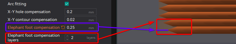
Elephant foot compensation
Mode: Advanced.
Variables: elefant_foot_compensation, elefant_foot_compensation_layers.
This feature compensates for the "elephant foot" effect, which occurs when the first few layers of a print are wider than the rest due:
- Weight of the material above them.
- Thermal expansion of the material.
- Bed temperature being too high.
- Inaccurate bed height/Leveling.

To mitigate this effect, OrcaSlicer allows you to specify a negative distance that will be applied to the first specified number of layers. This adjustment effectively reduces the width of the first few layers, helping to achieve a more accurate final print size.
The compensation works as follows:
When \(\mathrm{current\_layer} \le \mathrm{input\_compensation\_layers}\)
According to the equation, we can establish the following rules:
- In the 1st layer, since it is layer
1 - 1 = 0, compensation is 100%. - The intermediate layers (between the first and input_compensation_layers) will have linear compensation.
- Layers above the specified amount will not be compensated.
Assuming the compensation value is 0.25 mm:
- Elephant Foot Compensation Layers = 1 :
- 1st layer:
0.25mmcompensation (100%) - 2nd layer and beyond: No compensation (0 mm)
- 1st layer:
- Elephant Foot Compensation Layers = 2 :
- 1st layer:
0.25mmcompensation (100%) - 2nd layer:
0.25 − (0.25 / 2) × (2 - 1) = 0.125mmcompensation (50%) - 3rd layer and beyond: No compensation (0 mm).
- 1st layer:
- Elephant Foot Compensation Layers = 5 :
- 1st layer:
0.25mmcompensation (100%) - 2nd layer:
0.25 − (0.25 / 5) × (2 - 1) = 0.2mmcompensation (80%) - 3rd layer:
0.25 − (0.25 / 5) × (3 - 1) = 0.15mmcompensation (60%) - 4th layer:
0.25 − (0.25 / 5) × (4 - 1) = 0.1mmcompensation (40%) - 5th layer:
0.25 − (0.25 / 5) × (5 - 1) = 0.05mmcompensation (20%) - 6th layer and beyond: No compensation (0 mm).
- 1st layer:
Note
This feature will look like the part have a smaller footprint on the build plate in the preview, but the final print (if calibrated correctly) will have the correct dimensions after slicing.
That's why the Brim may look disconnected from the object when this feature is enabled. But in the final print, the brim will be correctly attached to the object.
If you use a high value for the Elephant Foot Compensation Distance, you may want to enable the Brim use EFC outline option to ensure proper brim attachment.
Elephant Foot Compensation Density
Mode: Expert.
Variable: elefant_foot_layers_density.
Controls the internal solid infill density used on Elephant Foot Compensation layers above the bottom layer.
This helps reduce excess material buildup and ripple/nozzle-scrape artifacts on early solid layers when first-layer squish is high.
- Range:
50%to100% - Default:
100%(feature disabled)
This option works together with Elephant foot compensation layers. For each compensated layer above the bottom layer, OrcaSlicer applies:
Where:
elefant_foot_layers_density= 80%.elefant_foot_compensation_layers= 4.layer_id= Layer number, starting from 1 for the bottom layer.- Bottom Shell Layers >
elefant_foot_compensation_layers. Otherwise, the adjustment will be applied only to the number of internal solid infill layers available.
Results in:
- 1st layer - Uncompensated , normal internal solid infill density (
100%). - 2nd layer - 1st compensated layer:
80%density. - 3rd layer - 2nd compensated layer:
85%density. - 4th layer - 3rd compensated layer:
90%density. - 5th layer - 4th compensated layer:
95%density. - Higher layers: normal internal solid infill density (
100%).
Note
This only affects internal solid infill inside the compensation zone.
It does not change sparse infill, top surfaces, or the bottommost layer.
Start with 80-90% and 1-2 compensation layers, then tune based on visible ripples or nozzle scraping on lower solid layers.
Precise wall
Variable: precise_outer_wall.
The 'Precise Wall' is a distinctive feature introduced by OrcaSlicer, aimed at improving the dimensional accuracy of prints and minimizing layer inconsistencies by slightly increasing the spacing between the outer wall and the inner wall when printing in Inner Outer wall order.
Technical explanation
First, it's important to understand some basic concepts like flow, extrusion width, and space.
Slic3r has an excellent document that covers these topics in detail. You can refer to this article.
Slic3r and its forks, such as PrusaSlicer, SuperSlicer and OrcaSlicer, assume that the extrusion path has an oval shape, which accounts for the overlaps. For example, if we set the wall width to 0.4mm and the layer height to 0.2mm, the combined thickness of two walls laid side by side is 0.714mm instead of 0.8mm due to the overlapping.
- Precise Wall Off

- Precise Wall On

This approach enhances the strength of 3D-printed parts. However, it does have some side effects. For instance, when the inner-outer wall order is used, the outer wall can be pushed outside, leading to potential size inaccuracy and more layer inconsistency.
It's important to keep in mind that this approach to handling flow is specific to Slic3r and its forks. Other slicing software, such as Cura, assumes that the extrusion path is rectangular and, therefore, does not include overlapping. Two 0.4 mm walls will result in a 0.8 mm shell thickness in Cura.
OrcaSlicer adheres to Slic3r's approach to handling flow. To address the downsides mentioned earlier, OrcaSlicer introduced the 'Precise Wall' feature. When this feature is enabled in OrcaSlicer, the overlap between the outer wall and its adjacent inner wall is set to zero. This ensures that the overall strength of the printed part is unaffected, while the size accuracy and layer consistency are improved.
Precise Z Height
Mode: Advanced.
Variable: precise_z_height.
This feature ensures the accurate Z height of the model after slicing, even if the model height is not a multiple of the layer height.
For example, slicing a 20mm x 20mm x 20.1mm cube with a layer height of 0.2mm would typically result in a final height of 20.2mm due to the layer height increments.
By enabling this parameter, the layer height of the last five layers is adjusted so that the final sliced height matches the actual object height, resulting in an accurate 20.1mm (as shown in the picture).
- Precise Z Height Off

- Precise Z Height On

Polyholes
Mode: Advanced.
Variables: hole_to_polyhole, hole_to_polyhole_threshold, hole_to_polyhole_twisted.
A polyhole is a technique used in FFF 3D printing to improve the accuracy of circular holes. Instead of modeling a perfect circle, the hole is represented as a polygon with a reduced number of flat sides. This simplification forces the slicer to treat each segment as a straight line, which prints more reliably. By carefully choosing the number of sides and ensuring the polygon sits on the outer boundary of the hole, you can produce openings that more closely match the intended diameter.

- Original implementation: SuperSlicer Polyholes
- Idea and mathematics: Hydraraptor